
The Calpine team attended the introduction to Grounding and Earthing course provided by E&S Grounding Solutions. The course we attended comprised of two online sessions of two hours each and covers the basic concepts of grounding and is a good introduction to subject. The instructors, David and Jeffrey have a very relaxed style that engaged the team to participate and ask questions. I recommend this course for people of all technical abilities who want to gain an understanding of the basics of Grounding & Earthing.
About E&S Grounding Solutions
What we do
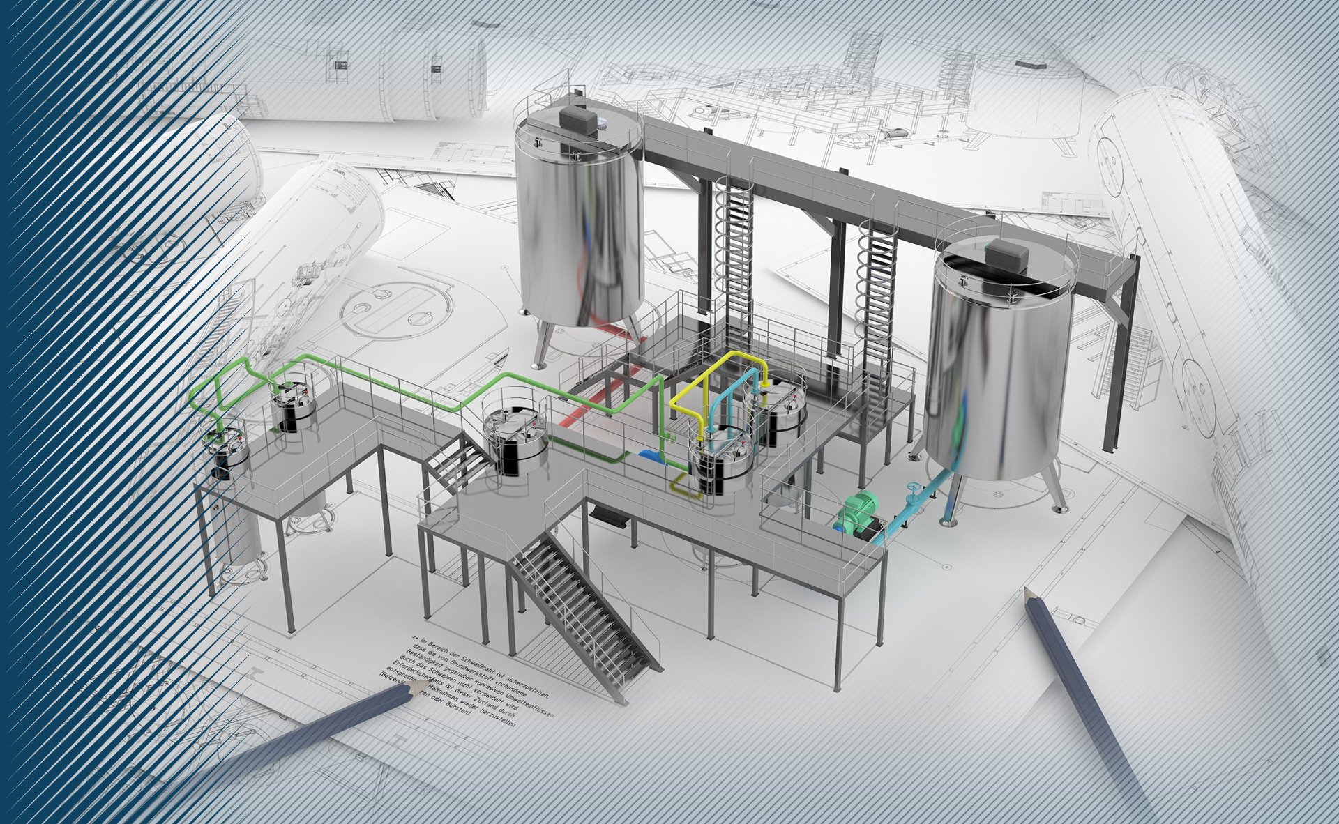
With over 18 years of dedicated grounding installations all across the USA plus numerous electrical engineering books published we are very proud to have received some incredible feedback from customers. Thanks to them and our undying passion for electrical engineering we consider ourselves true experts in the field of Grounding Design. Today we specialize in providing best-in-class electrical grounding services as well as live on-line training on an international scale. By utilizing leading industry computer modeling software we are able to provide highly sophisticated grounding design solutions that reduce costs and provide timely accurate solutions for our clients.
Our experienced electrical grounding design staff has already provided thousands of field site designs and continue to do so on a daily basis. Since we are a tight knit group of electrical engineers with a true passion for what we do we strive to deliver excellent personal service by working closely with all our clients, regardless of the scope of the project. Forming these type if productive working relationships allow us to deliver some of the most comprehensive electrical grounding design solutions in the market place today. We look forward to hearing and working with you.

Grounding & Earthing Overview
Electrical grounding or “Grounding” originally began as a safety measure used to help prevent people from accidentally coming in contact with electrical hazards. Think of your refrigerator. It is a metal box standing on rubber feet with electricity running in and out of it. You use magnets to hang your child’s latest drawing on the metal exterior.
The electricity running from the outlet and through the power cord to the electrical components inside the refrigerator are electrically isolated from the metal exterior or chassis of the refrigerator. If for some reason the electricity came in contact with the chassis, the rubber feet would prevent the electricity from going anywhere and it would sit waiting for someone to walk up and touch the refrigerator. Once someone touched the refrigerator the electricity would flow from the chassis of the refrigerator and through the unlucky person possibly causing injury. Grounding is used to protect that person.
By connecting a green ground wire from the metal frame of the refrigerator, if the chassis inadvertently becomes charged for any reason, the unwanted electricity will travel through the wire back to your electrical panel, and tripping the circuit-breaker stopping the flow of electricity. Additionally, that wire must be connected to something that is in turn connected to the earth or ground outside. For more information about Grounding click below.


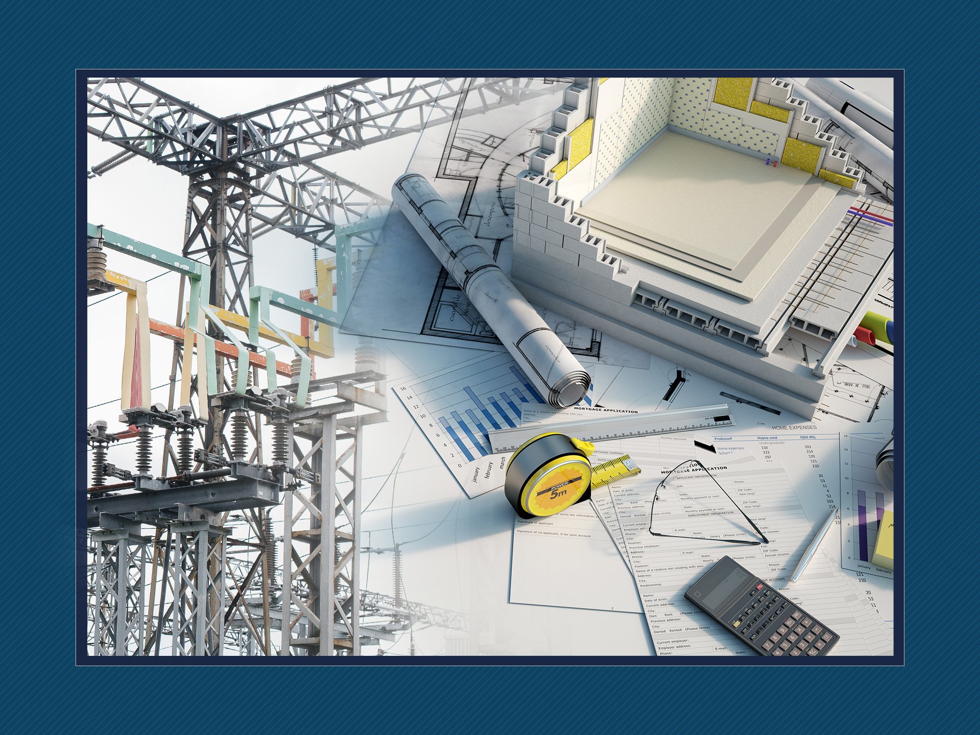
Services Overview
Providing best in class electrical grounding services to our customers is our top priority at E&S Grounding Solutions. In meeting our commitments of providing full-service electrical grounding services and top grounding design we rely heavily on using the latest computer modeling software created by Safe Engineering Services & Technologies ltd. (SES TECH) to plan and simulate the most viable and streamlined grounding solutions.
In addition we offer the following list of services:
- On-line Training
- Electrical Engineering
- ESRAP (Remote Assistance)
- Grounding Evaluation
- Power Quality Monitoring
- Grounding Requirements
- Lightning Risk Analysis
- System Design
- Resistivity Testing
- Ground Potential Rise (GPR)

Training Overview
Virtual Instructor-Led Training simulates the classroom experience in a virtual environment, providing Attendees the benefits of on-line convenience at reduced cost, with the real-time access to senior-level instructors. We offer training from theoretical and classroom training for engineers, to hands-on-in-the-field training for technicians.
All courses are customizable to fit for your company’s specific needs. Our instructors are renowned industry engineers who have worked with clients such as Con Edison, Google, DWP and many other well-known institutions. Join us in "Zoom" sessions as we take you through the most comprehensive grounding and earthing live training ever conceived on-line.
With over 18 years of seminar training plus several awards of excellence, E&S Grounding is on-line certified by professional LMS EDU platforms.
For more information on courses and modules offered please click below to access our training microsite.

Client Testimonials
Mick Deacon
Manager Electrical Engineering
E&S Grounding instructors David Stockin and Jeffrey Drummond have strong theoretical and practical backgrounds in grounding for industrial, utility, and generating plant applications, but more importantly, they are effective teachers. Our employees and extended enterprise customers have benefited from their deep understanding of basic grounding concepts, safety considerations, field testing, and troubleshooting, and advanced engineering concepts.
Brian Snyder
Solutions Director, Professional Services

The Petro Guardian team recently had the opportunity to bring in the E&S Grounding Solutions team for training and we appreciated the flexibility their course offered. The E&S team adapted their curriculum to meet our unique needs, which kept our group engaged and attentive throughout the entire class. They were able to take advanced subject matter, like 3-point fall-of potential and ground loop testing, and present it in a way that was understandable no matter what their experience level may have been.
Robert Morris
President
Our Resort Operator and Developer Clients demand the highest quality and the highest degree of protection for their critical systems. HydroDynamic Solutions always looks to E&S Grounding Solutions to provide a multitude of specialized services to include but not limited to power quality analysis, critical system grounding design, human safety electrical studies, and lightning risk assessments. Poised to react very quickly, E&S provides a readily deployable expert team to service our every need as a Utility Contractor.
Alan Davies
President/Owner

Have general grounding Questions?
Click here to: "Ask The Experts"
The E&S Executive Team
David Stockin, is the author of numerous prestigious publications regarding electrical grounding and earthing and is an often sought after expert in the field. David has been a full-time Grounding Engineer for over 20 years.
His list of publications include:
McGraw-Hill’s UK Wiring Standards for Earthing & Bonding (2016), McGraw-Hill’s National Electrical Code 2014 Grounding &
Earthing Handbook (2014), Standard Handbook of Electrical, Engineers, 16th Edition (2012), Standard Handbook of Electrical Engineers, 15th Edition (2008), Handbook of Electrical Power Calculations, 4th Edition (2014), and Handbook of Electrical Power Calculations, 3rd Edition (2000).

David Stockin
Founder CEO and Managing Partner
Our Lead Electrical Engineer and Engineering Trainer, has a Master of Engineering (M.Eng.) from Harvey Mudd College in Claremont, California and is a licensed Professional Engineer (P.E.) in California, Oregon, Washington and Idaho.
Mr. Drummond is the author of numerous publications regarding grounding, bonding and earthing and he remains a distinguished member of the following valued organizations we are proud to be apart of:
Tau Beta Pi, National Engineering Honor Society IEEE, Industrial Applications Society (IAS), Power & Energy Society (PES), and International Society of Automation (ISA).

Jeffrey D. Drummond, P.E.
CTO and Lead Electrical Engineer
Our Chief Operating Officer has a long career of executive management and leadership experience in a diverse range of industries to include aerospace, machine tools, computer peripherals, cryogenic/nuclear components, food manufacturing, and high-speed automation. Joe’s proven track record of senior leadership achievements in engineering, operations, quality assurance, and systems improvements have resulted in significant increases in efficiencies, profitability, and innovation. Joe’s focus for E&S is to continually increase organizational performance and refine the E&S Value Proposition, while leading a blend of motivation and innovation throughout the firm. B.S.B.A. and Aeronautical Engineering/UMASS.

Joe Plourde
COO / VP of Business Development


Books we wrote and co-authored
14 Years of industry certified and approved text books and handbooks only available on Amazon.
See our full list of titles and order them online.
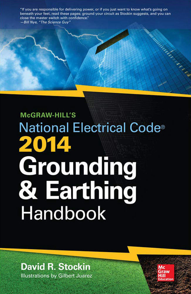
McGraw-Hill - 1st Edition
NEC 2014 Grounding & Earthing Handbook
Fully discusses above-grade wiring issues and below-grade earthing issues related to electrical grounding in conjunction with Article 250 of the 2011 National Electrical Code. This practical guide features easy-to-understand language and real-world examples throughout.

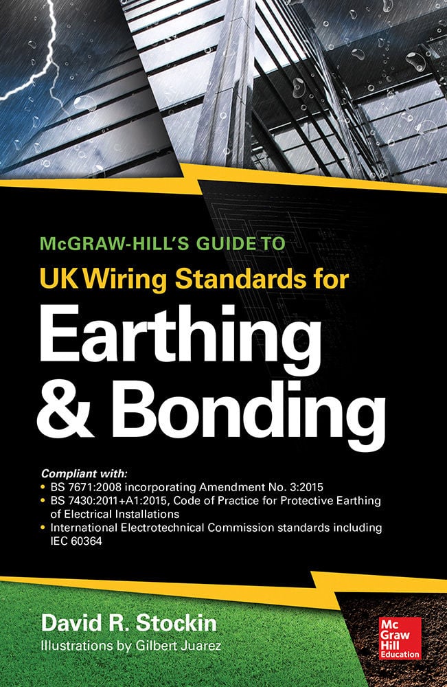
McGraw-Hill - 1st Edition
UK Wiring Standards for Earthing & Bonding
Addresses the above-grade grounding and below-grade earthing issues related to Article 250 of the 2014 National Electrical Code. This practical guide features in-depth discussions of each of the Code’s requirements, section by section, along with clear explanations and real-world examples.

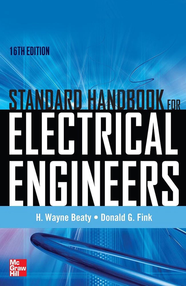
16th Edition
Standard Handbook for Electrical Engineers
LThe Standard Handbook for Electrical Engineers has served the EE field for nearly a century. Originally published in 1907, through 15 previous editions it has been a required resource for students and professionals. The 16th edition was published on August 30, 2012.

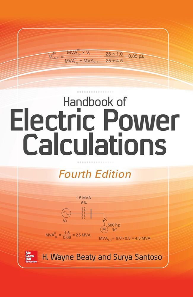
4th Edition
Handbook of Electric Power Calculations
A bestselling calculations handbook that offers electric power engineers and technicians essential, step-by-step procedures for solving a wide array of electric power problems. This edition introduces a complete electronic book on CD-ROM with over 100 live calculations.

